Overload relay is an important component in protecting motors from electrical overloads. By monitoring the current flow to motors, these devices prevent damage that could affect motor performance and longevity. This article explores the principles, their types, applications, and their benefits in maintaining motor health and efficiency.
Working Principle of Overload Relay
Overload relays operate based on two primary types: thermal and electronic. This relay uses the principle of thermal expansion to trigger a protective response when excessive current causes undue heat buildup. Electronic relays employ sensors to monitor current levels with precision. Both types aim to protect equipment from overload conditions, such as overheating or system failure.
Overload relays protect motors from excessive currents that can cause overheating and damage. They continuously monitor the electrical current flowing to a motor and cut off the power supply when the current exceeds the motor’s designed threshold.
This intervention prevents overheating, preserves the motor’s structural integrity, and extends its service life. Thermal overload relays use bimetallic strips that bend with increased heat from excess current, triggering a switch to disconnect power.
In addition to protection, they contribute to operational efficiency by preventing unnecessary downtime caused by equipment failure. This means less time spent on repairs and more on productivity. The integration of smart technology within electronic relays enables real-time monitoring capabilities, allowing precise control over motor functions and facilitating preventive maintenance strategies.
Construction of Overload Relay

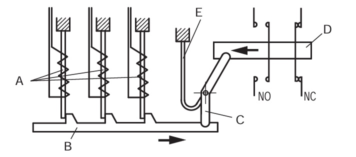
- A-Indirectly heated bimetal strips
- B-Trip Slide
- C-Trip Lever
- D-Contact Lever
- E-Compensation bimetal strip
Thermal overload relay construction is simple it has three bimetallic stripes as shown in the above diagram. the bimetallic strips get heated by an overcurrent drawn by the induction motor, causing them to bend and activate the trip mechanism.
The release mechanism actuates an auxiliary switch that breaks the coil circuit of the motor contactor.
Parts of a Thermal Overload Relay

Terminals
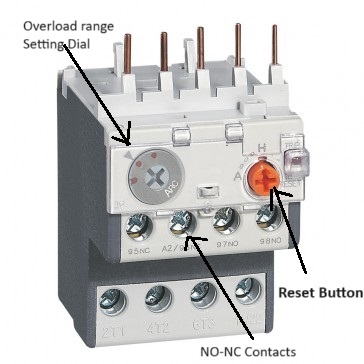
L1, L2, and L3 are terminals that are connected to the contactor of the starter. Output Terminals T1, T2, and T3 are wired to the motor.
Overload Setting Dial
There is one small circular dial provided on OLR that is used to set the overload ampere setting. As the motor current reaches this preset value relay will trip.
Overload Reset Button
If the relay tripped on overload condition after diagnosing the cause, we can reset the relay using this reset button.
Auto-Manual Reset selection
Using this selection switch you can choose between manual and automatic RESET. A device set to manual RESET needs to be reset manually by pressing the RESET button provided on the relay.
if the selection is set to auto mode, the bimetallic relay will reset automatically after cooling down of the bimetallic strip. No manual rest is required.
TripTest Button
this button is particularly used to test relays tripping mechanism working or not.
Auxillary Contacts
Auxiliary contacts are used for indication purposes. NC contact of thermal overload relay connected in series with a control circuit to trip motor in case motors draws excessive current than full load. NO contact of the relay is used for trip indication.
Types of Overload Relays
- Bimetallic thermal relays use two metals with different expansion rates when heated, triggering a mechanical action to interrupt the circuit. This simple yet effective mechanism is ideal for environments where endurance against high temperature fluctuations is crucial.
- Electronic overload relays provide precision and speed, utilizing current transformers and temperature-sensitive elements for real-time monitoring and action. These relays excel in applications requiring meticulous control over motor operation, particularly where frequent starts and stops are common.
- Melting alloy thermal overload relays use a solder that melts under excessive current, activating a mechanical release. This method is favored for its robustness in resisting mechanical shock, making it a reliable choice for settings that benefit from its distinctive reset procedure.
Advantages and Disadvantages of OLR
Advantages
- Overload relays protect these motors against potential overload conditions that could lead to overheating.
- Prevent damage to the motor windings or insulation
- Accuracy is high
- Easy to install
- Available for a wide range of current setting
- Automatically or manual reset facility available
- Cost-effective
Disadvantages
- Slower response time
- Required time to cool down the bimetallic strip after the trip. hence can not be taken in line immediately after the trip
- Not provide short-circuit protection

