Direct On-Line is the simplest and cheapest method used for starting a three-phase induction motor. DOL starter is used for up to 5 HP motors. this starter is more popular due to the low price.
Different starting methods are used to start 3-phase induction motors like star delta starter, autotransformer starter, variable frequency drive, soft starter.
DOL starter directly applies full line voltage to the induction motor and the asynchronous motor draws a very high starting current up until it achieves full speed. This starting current is up to 6 to 7 times of full load current.
In this article, we will discuss the DOL starter Working Principle and Construction, as well as the control circuit diagram and power circuit wiring for Single and three-phase motor starters.
DOL starter connects the motor directly to the supply without a reduction in supply voltage and applies full line voltage to the 3-phase motor. this is the main disadvantage of this starter.
A small HP motor can be started simply by plugging into the power supply. But a large HP motor required a special unit called a motor starter.
Direct online starter for 3-phase induction motors contains parts like miniature circuit breakers (MCBs) for motor protection purposes, overload relay, power contactor, fuse unit, start buttons, and stop buttons.
Small size starter is operated manually but for larger HP motors, it is operated using an electromechanical contactor to switch the motor ON and OFF.
DOL Motor Starter can be used if a high starting current cannot cause an excessive voltage drop in the motor circuit.
It finds applications in various industries where the motor load is relatively small and does not require precise control.
Table of Contents
DOL Starter Control Diagram
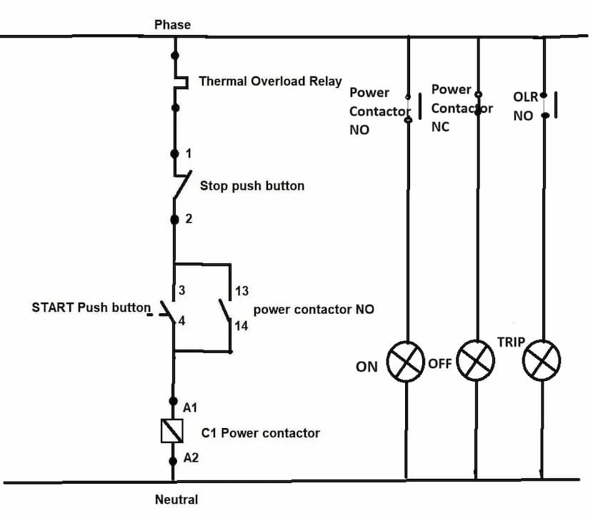
DOL starter control Diagram consists of components like the Main power contactor, start button, stop push button, and overload relay are connected in series, this circuit is called the control circuit. This circuit controls all control of the starter. The above diagram shows the control wiring diagram.
Star and stop push buttons are provided for starting and stopping operations.
A NO (normally open) contact on a power contactor is utilized as a holding contact to maintain the contactor in a latched state.
As shown in the control wiring diagram overload relays NC contact connected in series to isolate three phase induction motor from the supply in overload condition.
Power Diagram
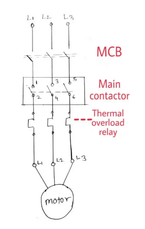
Power circuit Diagram consists of MCB or fuse unit which is connected in series with the supply. Power contactor, thermal overload relay for protection, stop and start push button for starter and stop operation.
DOL Starter Working Principle
The working principle is relatively straightforward. When the DOL starter is switched on, it creates a direct electrical connection between the motor and the power supply. This means that the induction motor receives the full voltage from the power supply, allowing it to start running immediately.
To start the induction motor, the start push button needs to be pressed. After that, the main power contactor coil is energized due to electromechanical action and this latch contactor pole. applies full line voltage to the motor terminals. and the motor starts running. The motor will draw a very high inrush current for a short time.
After that start push button gets released and the supply to the contactor coil continues through the holding contact provided to the main contactor of the DOL starter.
As the motor accelerates and heads towards full speed, the current begins to drop but it will not drop significantly till the motor achieves full speed, about 85% of synchronous speed.
The motor load will affect the time taken for the motor to accelerate to full speed and therefore the duration of the high starting current, but it will not affect the magnitude of the starting current.
the torque developed by the motor exceeds the load torque at all speeds during the start cycle, the motor will reach full speed. If the torque developed by the motor is less than the torque of the load at any speed during the start period. the motor stops accelerating.
If the motor torque developed by the DOL Motor starter is less for load, then the motor must be replaced by the motor which can develop high starting torque.
At the time of stopping the motor we need to press the stop push button on the dol starter circuit, this disconnects the supply to the coil, and the contactor coil gets de-energized, and it releases the contactor latched pole, and the motor supply gets disconnected.
Components
Contactor
A contactor is a heavy-duty relay with a high current rating, used to connect an electrical motor to the power supply.
The current rating of contactors varies from 10 amps to several hundred amperes. The large contactor is made from an alloy containing silver.
Arcing during the switching operation of the contactor causes contact to oxidize. However, silver oxide is still a good conductor.
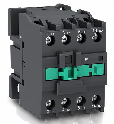
Overload protection is provided along with the contactor to protect the motor from overloading. A contactor is not used to interrupt a short circuit current, Unlike the circuit breaker.
The contactor creates noise while switching operations. If when requires silent operation solid state relay is used. A contactor is an electromechanical switch that operates on energizing and de-energizing the contactor coil.
The contactor has three main power contacts depicted as L1 L2 L3 in the DOL starter wiring diagram. the contacts that connect a motor to the power supply and also have additional contacts are referred as Auxiliary contacts, which act as hold-on contacts when starting push-button release. To maintain energization of the contactor coil. auxiliary contacts are also used for indication and feedback purposes.
Thermal Overload Relay
Most motor winding failure occurs due to overload. Motor overload tends to the heating of winding that results in the weakening of its insulation. A minor overload does not cause a motor failure immediately but it will eventually shorten the expected lifetime.
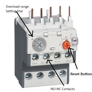
To prevent this situation thermal overload relay or OLR is provided in a Direct Online starter. Thermal overload relay has a bimetallic strip that bends because of overheating caused by overcurrent.
resulting in disconnecting the motor from the supply and preventing further motor winding damage also insulation failure.
Miniature circuit breaker
A miniature circuit breaker (MCB) is a Switch that automatically disconnects the motor from the supply when an abnormal condition happens.
To protect the motor from short circuit conditions and avoid damage to motor winding MCB is used in circuit.
generally, MCB is used in circuits in place of conventional fuses
Push buttons
There are two push buttons used in the dol motor starter circuit, one is a green color for the start button and the other is red for the stop push button.
Start push button
this is normally an open-type push button, to start the motor, this push button needs to be pressed to start the motor, and the supply gets applied to the motor through a power contactor.
Stop push button
This is the NC type of push button we need to press to stop the motor from running condition. after pressing the stop button contactor coil gets de-energized with the opening of contacts. Due to this switching operation motor gets disconnected from the supply and the motor stops rotating.
Indication lamps
Indication lamps are used in the DOL starter circuit to indicate the status of the motor. generally, three types of indication lamps are used in direct online starters green for motor off indication, red indication lamp to indicate the motor is running and third assigned to trip.
Advantages of direct online starter
- Direct On-Line motor starter is the Cheapest Motor Starter.
- DOL is the simplest motor starter to design and maintain.
- 100% starting torque.
- This starter is used up to 5HP motor depending upon insulation class of motor.
Disadvantages
- High starting current
- typically 7 to 8 time rated current applied at starting
- due to high current stress applied on motor winding.
- not suitable for high-rating motors.
- create a voltage dip in the power system
- High starting torque
Applications
- D O L starters are mainly used to start smaller rating motors up to 5HP
- It finds applications, where the starting current does not cause a huge voltage dip in the system
- used for applications that required high initial torque
- They are commonly used in pumps, fans, small motors, compressors, small water pumps, and industrial conveyor belts. Fans, air curtains, exhaust fan, blower etc. These applications benefit from the simplicity and cost-effectiveness of DOL Starters, as they do not require complex control systems or precise speed regulation.
Comparison of D O L Starter and Star-Delta starter
| Sr No | DOL Starter | Star Delta Starter |
| 1 | This starter is used up to 5HP motor | It can be used up to 20HP motor |
| 2 | Starting currently is so high | The starting current is reduced by 1/3 |
| 3 | Construction is simple | wiring is complex compared to the DOL starter |
| 4 | Can be used with any motor i.e start connected or delta-connected motor | only used where all six winding terminal leads are accessible |
| 5 | Starting Torque is high | The starting Torque is low |
